
Ventilation design from room type to printed sheet
A room type gives an airflow proposal, a duct that ends on another duct joins it with a branch, and sizing and balancing happen in the same window as the drawing. Limits show their sources.
What you draw and calculate
Airflows from room types
When a room has a type, PirtoCAD proposes its supply and extract airflows and names the document each value comes from. A preview shows the proposal before anything is written. Values you have typed yourself are kept unless you select the room to receive the proposal. The proposal is a starting point; the designer decides the final airflows.
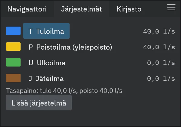
Air handling unit, ductwork, branches and air terminals
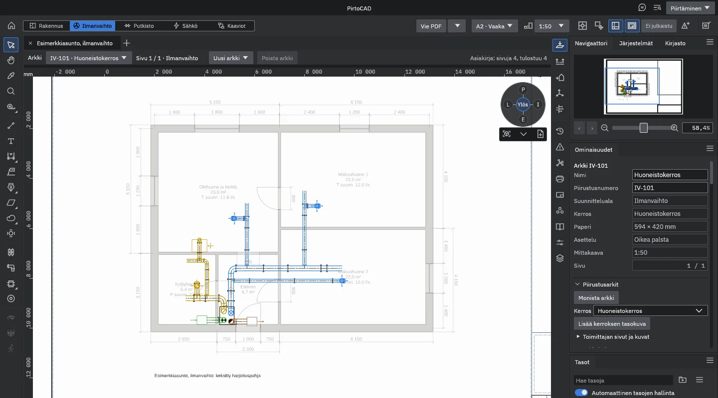
Place the air handling unit, draw the supply and extract ducts and connect the air terminals. A duct drawn to end on another duct at the same level joins it with a branch. A duct can be taken under or over another from the Ventilation menu, the context menu or the Problems panel. At the open end of an outdoor air or exhaust air duct, the Problems panel proposes an air terminal instead of a cap: an outdoor grille for outdoor air and a roof exhaust pipe for exhaust air.
Sizing, balancing and problems
The Size the system button (Mitoita) in a system's properties first shows a preview: for each round duct, its airflow, velocity and pressure loss at the current and the proposed size, with every limit and its source. Clicking Apply the sizing then changes the sizes in one undo step. Balance writes the valve settings and the damper pressures into their tags. Calculation findings, such as a valve that cannot reach its airflow, appear in the Problems panel.
- Duct pressure loss by Darcy-Weisbach with Colebrook-White friction, fittings by loss coefficients
- Tightness class per system; a class below the minimum in Finnish decree YM 1009/2017, section 20, appears in the Problems panel
- SFP limit by the date the building permit was applied for
- The duct sizing profile follows the building's use until you choose another
 Video coming
Tags, sheets and quantities
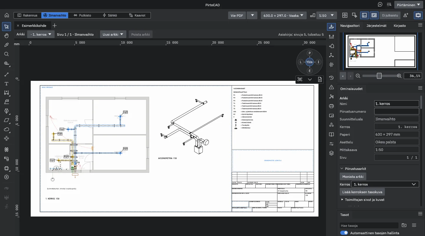
Tag the air terminals and add a legend, an isometric view and sections to the sheet. A shaft's riser diagram opens in a view of its own but cannot yet be placed on a sheet. Export the sheets to PDF and the material take-off rows to Excel.
Limits with their sources
The Calculation values view shows every value the calculation uses, with its unit, the shipped default and its sources, and where the value in use comes from. Most values can be changed, and every change is one undo step.
| Check | Source | Where it shows |
|---|---|---|
| Minimum ductwork tightness class: B, or C for systems carrying contaminated or hazardous extract air | YM 1009/2017, section 20 | System properties, Problems |
| SFP limit by the permit application date | YM 1010/2017, section 30; earlier regulations by application date | Calculation panel, the system's limits |
| Supply and extract airflows by room type | FINVAC 2019 guide (based on YM 1009/2017) and RakMK D2 2012; the stricter value applies | Room properties, preview |
The designer is responsible for the results. Defaults help, but a calculation is only as reliable as its input data. An empty Problems panel only means that the program's current checks found nothing. It does not mean that the design has been checked or that it complies with regulations.
Coming to ventilation
These are in progress and not yet in the alpha:
- Sound level calculation duct by duct; until then acoustic sizing relies on the velocity limits (LVI 30-10333)
- Ductwork leakage in the airflow and pressure loss calculation
- Tightness class check for extract ducts under positive pressure
- Room air balance through transfer air paths
- Calculation of natural ventilation and of radon, combustion air and transfer air systems
- Room airflow simulation
The ventilation designer's path
The planned path is the foundations course first, then the ventilation course, which moves from a one-storey house to a two-storey one. No episodes have been published yet.
 Video coming
V1.1 One-storey house: the air handling unit
Video coming